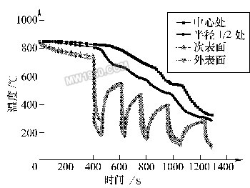
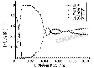
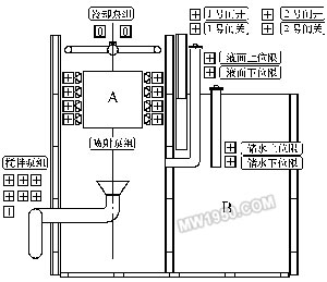
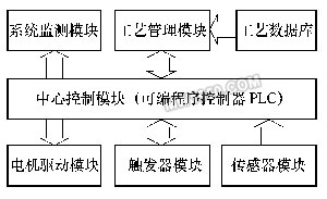
Third, the development of quenching and cooling process during 裓-ring control The quenching and cooling process of 裓-ring control should comprehensively consider the shape, size, material and quenching requirements of microstructure, mechanical properties, stress and strain state. Therefore, it must be based on numerical simulation technology and combined with experimental verification. Taking the long axis of f220mm (material is 42CrMo) as an example, Figure 2 shows the change of temperature around the surface of the shaft and the subsurface to the center after a series of 裓-ring cooling processes. Figure 3 shows the corresponding final tissue score. Figure 2 shows the simulated temperature change process Figure 3 shows the final tissue component of the simulation Through the method of numerical simulation calculation, the preset process can be comprehensively predicted and analyzed. Under the premise that the simulation data can meet the expected requirements of quenching treatment, further verification of the process parameters can be used to obtain a relatively effective and feasible actual treatment process. The table listed is the mechanical properties of the long circular shaft at 1/2 radius after the above series of cooling and quenching treatment (after quenching and tempering treatment). Mechanical properties at the radius of 1/2 of the long axis (after quenching and tempering) Fourth, the design and implementation of 裓-ring control quenching and cooling equipment Conventional quenching equipment cannot meet the needs of the quenching and cooling process during helium-ring control. Especially for large and complex workpieces, if the traditional sink and crane are used for quenching and cooling, it can not adapt to the rapid and frequent water quenching and air-cooling conversion of the workpiece, and can not achieve precise control of the cooling time. Therefore, it is necessary to design special equipment to meet the process. Requirements for the equipment. For example, quenching treatment of large crankshafts, large die steel and other workpieces, Shanghai Jiaotong University has developed a quenching tank device with corresponding functions to meet the process requirements (as shown in Figure 4). Figure 4 CTQP quenching and cooling equipment In the figure, part A is the quenching cooling zone of the workpiece, and the B position is the liquid storage zone. The workpiece is suspended in the A position in the figure. In the water quenching process, the jet arrays located on both sides of the workpiece position rapidly inject the medium into the A position to achieve the immersion quenching of the quenching member. When converted to air cooling, the valve below the A position opens, the water in the quenching cooling zone quickly flows into the B zone, and the quenched parts in the A zone are air cooled. The biggest feature of this design is that it can replace the traditional workpiece immersion liquid immersion method to achieve immersion liquid quenching, which is especially suitable for the processing of large-sized workpieces. At the same time, the reliability and stability of the equipment are larger than that of the lifting equipment. For improvement. Since the water injection system adopts the design of the multi-point injection array, the water injection system can also provide various cooling means such as water spray and spray, which enables the quenching tank to perform various composite treatments on the workpiece. Five, 裓-ring control quenching cooling control In order to realize the 裓-ring control quenching and cooling process, in addition to designing the functional quenching tank described above, a corresponding control system is also needed to realize. This control mode needs to consist of three levels of structure, as shown in Figure 5. From bottom to top, the electrical drive layer, PLC control layer and software management layer. Figure 5 CTQP control structure (1) The electric drive layer mainly includes: motor drive module for driving various types of motors, fans, pumps; trigger module for auxiliary driving other non-high-power mechanisms, such as solenoid valves; sensors The module connects various sensor components on the device and collects various data parameters throughout the process. (2) PLC control layer The core of this level is PLC (programmable controller). It down-controls and controls the various operations of the electrified driver layer, returns various data information upwards, and accepts management information sent by the software management layer for execution. The PLC (Programmable Logic Controller) currently widely used has a control cycle of up to the order of milliseconds. Its control capability and accuracy far exceed the traditional control instruments, thus providing more reliable and precise control for the quenching process. . (3) Software Management This level mainly provides human-machine interface and advanced management functions. As we have already discussed - the process of 裓-ring controlled quenching and cooling needs to be completed by complex numerical simulation and experimental verification. In the actual operation process, a large number of pre-simulation calculations and tests are needed to establish the necessary process. The database is used to provide a reliable data basis for the actual process generation of the workpiece, so the process database system is the core content of the software management layer. Conclusion The above analysis of the 裓-ring control quenching cooling diagnosis and the corresponding quenching equipment, the diagnosis and the equipment has been 綷 - in the enterprise has been successfully applied. It is hoped that through the promotion of this technology, enterprises will solve more problems that cannot be solved by traditional methods. Previous page
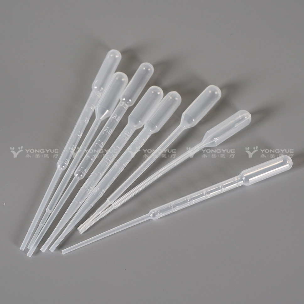
Practical disposable transfer pipettes, made from natural low density polyethylene (LDPE). The transfer pipet is simple and safe to use with a long shelf life; no issues with broken glass, cracked or loose bulbs. Additional advantage is that with the single piece design lager amount can be transferred by allowing fluids in the bulb. These plastic transfer pipettes are ideal for transferring small amounts of fluids for microscopy sample preparations or to prepare mixtures or staining solutions. The extra fine tip enables transferring minute amount of fluids. These cost-efficient plastic transfer pipettes are disposable and intended for one-time use. Ideal for educational and research environments. Can be used for fluids up to 70°C, please take care to protect the fingers squeezing the bulb. Available in six sizes/styles: 0.5ml, 1ml, 2ml, 3ml, 5ml, 10ml.
Plastic Transfer Pipettes,Disposable Transfer Pipettes,Sterile Transfer Pipettes,Disposable Plastic Pipettes,3ml Pipette,5ml Plastic Pipette,Pasteur Pipettes Yong Yue Medical Technology(Kunshan) Co.,Ltd , https://www.yongyue-tube.com