High-speed machining technology is a rapidly developing high-tech in the machinery manufacturing industry. It is widely used in mold manufacturing and can greatly improve the efficiency and quality of mold processing. Starting from the characteristics of high-speed machining, the general programming process of Cimatron software is discussed. The high-speed machining function and the cutting strategy of the software are analyzed. The common methods of cavity machining for NC machining are summarized.
As the key tooling for the production of new products, the design and production of molds has increasingly become the decisive factor for the new product development cycle. With the development of CNC machining equipment and high-performance machining tool technology, high-speed machining technology is applied to mold manufacturing, which can greatly improve the speed of mold processing, reduce the processing steps, shorten or even eliminate the repair work of the fitter, thus greatly shortening The production cycle of the mold. High-speed machining has special processing requirements different from traditional machining. CNC machining instructions contain all the processes, so the CNC automatic programming system for high-speed machining—the CAM system must meet the corresponding special requirements: (a) The CAM system shall have a high computational programming speed; (b) full automatic over-cutting processing capability and automatic toolholder interference checking; (c) provide a rich processing strategy that meets high-speed machining requirements; (d) feed Rate optimization processing function.
Cimatron is an excellent CAD/CAM software for the face mold manufacturing industry. It not only provides complete modeling, drawing, analysis and machining programming functions, but also provides an ideal solution for the entire manufacturing process of cavity molds. In particular, its application of original knowledge-based machining, automated NC and intelligent NC based on three technologies of blank residue makes it one of the most ideal high-speed programming software for cavity mode. The following is a combination of Cimatron's application in actual machining, and its programming process and high-speed machining methods and strategies for cavity molds.
1 Cimatron machining programming process
- Modeling
- The product can be modeled directly through Cimatron or converted to the IGES standard format using other CAD software.
- Become the model format of Cimatron. The specific operation process is: select application--IGES--read in Cimatron's DataInteface module, select igs file in the input field, and press Execute to complete the conversion of the part model format.
- Establish machining coordinate system
- Enter the Cimatron environment, open the part model, select the NC machining menu, the system prompts to select a machining coordinate system, if not, create a machining coordinate system. Cimatron offers four methods to create a machining coordinate system, usually using a three-point positioning method. The establishment of the machining coordinate system must be based on the principle of reasonable part clamping and convenient measurement. Generally, the center point of the upper surface of the part is the origin of the machining coordinate system.
- Tool setting
- In Cimatron, the tool definition is very flexible. When a machining process is selected, the system will automatically determine whether there is any tool in the tool library. If there is a system, the tool used last time is used by default. If there is no system, the tool definition menu is automatically displayed. , requires the definition of tool parameters.
- Step editing
- During the step editing process, it is required to determine which features can be completed in one setup, arrange the machining sequence and the tools used, and finally determine which machining method to use to complete these steps separately. A machining method has been selected, which requires the definition of the machining object, the machining range and the machining parameters (such as the speed, the feed rate, the amount of cutting per layer, the machining allowance, the feed pattern and the safety plane, etc.).
- After each parameter of each step is defined, the calculation of the tool motion trajectory is completed by software, and the machining simulation can be performed. When the trajectory is not ideal, the parameters can be re-modified and calculated. In some cases, direct programming of the trajectory can also achieve good results.
- Post processing
- After the tool path of all the steps is generated, it is converted to the machining G code by a dedicated post-processing program.
2 Cimatron high-speed machining module analysis and cutting strategy
The high-speed machining center has a preview function. When the tool needs to make a sharp turn, the machining center will pre-decelerate in advance, and then increase the speed after completing the turn. This function of the machine tool is mainly to avoid the inertia impact is too large, resulting in inertia overcut or machine tool spindle damage. When using Cimatron's CAM system for NC programming, it is necessary to ensure smooth and smooth tool trajectory. In addition, in high-speed machining, the speed of the tool is very high, and the tool used is usually small, so it is required to maintain a fixed tool load during the machining process to prevent the tool overload from damaging the machine spindle. Cimatron offers a variety of machining methods and tooling methods. 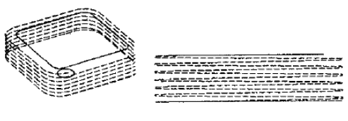
Figure 1 Spiral cut |
- Contoured spiral machining. The spiral machining is a spiral cutting down the closed contour with no advance and retraction in the middle, and the cutting process continues to be constant. Click CREATE-MILL-USR from the operation mode management table, right click, click helicprf.dll in the NC folder, define the parameters to generate a spiral tool (Figure 1).
- Cycloid contour machining. When selecting Profile processing, the TROCHOID high speed tool is recommended in the process parameter interface. The advantage of this approach is that it ensures that the machine removes the blank material with the most challenging process parameters, thus improving the cutting efficiency of the machine. It is suitable for narrow groove and cavity machining of high hardness materials (above HRC50) (Figure 2).
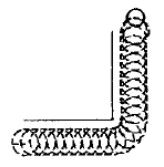
Figure 2 Trochodiai movement |
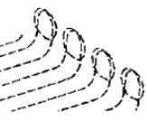
Figure 3 Internal arc transition tool (Inwards tangengial link) |
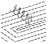
Figure 4 Arc fit rapid moves |
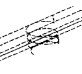
Figure 5 Inter-layer NURBS transition to (Connect layer with nurbs) |
- Curved cavity machining with unique shifting strategy. The process mode selects the surface cavity SRFPKT, and an HSM BET. PASSES ON/OFF switch is provided in the process parameter interface. When ON is selected and ROUGH or ROUGH + FINISH and PARALLELCUT are selected, the interface will pop up LOOPS INWARDS/LOOPSOUTWARDS/GOLFCLUB Move the knife strategy (Figure 3); select SPIRAL CUT, the interface will pop up ALL CORNER: ROUND / LOOP (Figure 4). This tool path can realize the smooth transition of the corner of the tool rail, ensuring that the tool feeds at a constant speed during the process of moving the tool, thus effectively reducing the vibration of the machine tool and avoiding the interference of the tool.
- Knowledge-based contour (WCUT) processing. In the process parameter interface of WCUT, in the ROUGH and ROUGH + FINISH state, the WITHSTOCK and MIN. WIDTH combination buttons can be used to judge the blank amount and perform intelligent secondary roughing.
In the FINISH state, select the YES function in HSM BETWEEN LAYERCONNECT YES/NO, and the NURBS smooth connection is used between the processing layer and the layer (Figure 5). The advantage is that the flat area and the steep area of ​​the curved surface to be processed are automatically recognized, so that the finishing allowance is more uniform and the surface quality is higher. 3 Cimatron cavity mold high speed machining programming strategy
In the three-axis CNC milling of cavity mold parts, the milling process from general shape blank to finishing before finishing is generally divided into roughing, semi-finishing, finishing and root cleaning. Roughing can be done by inserting, etc., but contoured (WCUT) milling has the most efficient roughing method with efficient round cutting and intelligent feed settings, as well as unique interlayer machining. Cimatron has a know-how based on blank residue that can be used to generate a tool path based on the condition of the blank. Using WCUT/ROUGH as a semi-finishing process and selecting the WITHSTOCK option in the machining parameters completely eliminates the empty knife phenomenon, and the cutting load of the tool is more reasonable and the trajectory is smoother. In the finishing process, SRFPKT and WCUT/FINISH are most commonly used. For the flat surface with the slope close to the horizontal plane, the SRFPKT process is better for the surface machining, while the steep surface with the slope close to the vertical surface is generally processed by the WCUT/FINISH process. . 4 Conclusion
With the increasing popularity of high-speed milling technology, more and more companies have begun to apply this technology in production practice. Programming is one of the key tasks and a creative work. Fully excavate and use Cimatron software's high-speed machining programming technology to make mold products go to market with high quality, high efficiency, long life, low construction time and low cost, and strive for more space. Optical Bandpass Filter
Optical Bandpass Filters are used to selectively transmit a portion of the spectrum while rejecting all other wavelengths. Optical Bandpass Filters are ideal for a variety of applications, such as fluorescence microscopy, spectroscopy, clinical chemistry, or imaging.
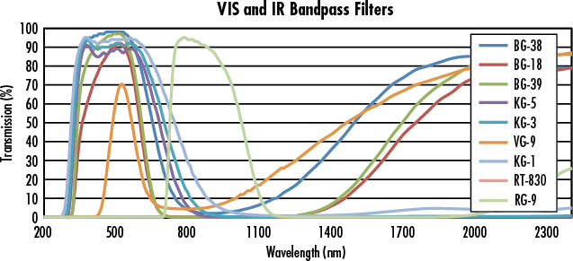
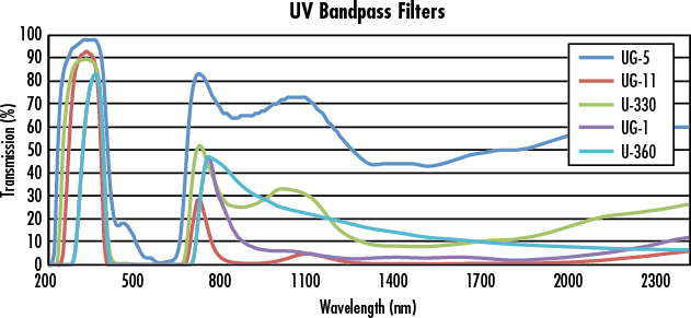
An optical bandpass filter has a transmission band surrounded by two blocking bands that allow only a portion of the spectrum to pass. These optical bandpass filters have broad spectral bandwidths in either the ultraviolet, visible, or infrared spectrums. The nearly black filters absorb visible radiation. They are perfect for ultraviolet or infrared detection applications. UV filters are often used to selectively transmit the 254nm and 365nm mercury lines. IR filters are often used in nightvision and IR sensing systems.
Color Separation Filter,Neutral Density Filter,Filter,Short/Long Wave Pass Filter,Bandpass Filter and Interference Filter available upon request.
Specification of our color filter as follow:
Material:Filter Glass,BK7
Dimension: 4mm-160mm - 0.20mm
Squares/Rectangles:1mm-165mm
Thickness:0.5mm-4mm
Wavelength range:190nm to 4.5um
Thickness tolerance:+/-0.01mm-0.1mm
Edges:Fine
Ground Flatness:Up to Lambda/10
Surface quantity: 80/50-20/10 Scratch/Dig
Optical Bandpass Filter,Optical Glass Bandpass Filter,Bandpass Filter Kits,Uv Bandpass Filter
China Star Optics Technology Co.,Ltd. , https://www.opticsrealpoo.com


