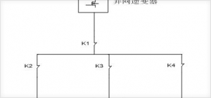
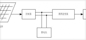
First, micro grid The microgrid system is a new type of network structure. It is a system unit composed of distributed power sources, loads, energy storage systems, and control devices. It is an autonomous system that can realize self-control, protection, and management, and can be connected to an external power grid. Running, it can also be run in isolation. The microgrid system is a concept relative to the traditional large grid system and refers to a network in which a plurality of distributed power sources and their related loads are formed according to a certain topology, and is connected to a conventional large power grid through a switch. The core equipment in the microgrid system is the distributed power supply and energy storage system, including photovoltaic grid-connected inverters, wind power grid-connected inverters, diesel engines, PCS, and BMS. In recent years, with the rapid development of microgrid systems, grid-connected inverters have been given a new definition: distributed photovoltaic power. It can be used as the main power supply of the microgrid system and it is one of the core technologies of the entire microgrid system. Because of the special nature of the power supply (current source), it can also be used as a supplemental power supply for the microgrid system. PCS, or energy conversion system, is a new type of distributed power supply with very flexible applications and powerful functions. It is also a kind of energy storage system. As a four-quadrant converter, it can implement both grid-connected inverter functions and grid-connected rectifier charging functions. It can also implement independent off-grid inverter functions. In the microgrid system, the distributed configuration of the distributed power supply is based on certain principles. Otherwise, it will cause excessive power supply or lack of power supply. The capacity of the grid-connected inverter should be less than or equal to the total load capacity, and the closest to the load capacity is the best. It must not be too small or too high. If it is too high, excess power cannot be absorbed and the system can easily crash. In recent years, research results have shown that when the capacity of the grid-connected inverter is greater than the total capacity of the load, if PCS is used as a support source at this time, the surplus power of the grid-tied inverter will be fed into the PCS to make the PCS “off-grid†state. This state is not stable. Currently, there is no real effective control method. Therefore, it is recommended that the capacity of the grid-tied inverter be less than or equal to the total load capacity. The PCS capacity should be set to 1.5 times the total load capacity, but the battery capacity needs to be configured in accordance with the system can withstand 3 to 5 days of rainy days. Although the grid-connected inverter can also provide power for the load, but the micro-grid system is running at night most of the time. At this time, the grid-connected inverter cannot work. Therefore, most of the power of the micro-grid system is provided by the PCS. Therefore, the capacity configuration of the PCS needs to take into consideration continuous rainy days and night conditions. Figure 1 shows the architecture of the microgrid system. The grid-connected inverter and the PCS are connected together to the system bus, and the bus is loaded with the load. (1) When the large power grid is not disconnected, if it is in the daytime, the system runs in the state of the grid-connected inverter as the main distributed power supply, and the PCS is in the state of charging the battery to serve as a standby power supply. If it is at night, the mains still supplies power to the load, and the PCS is still charging the battery as a backup power source. (2) When the large power grid is disconnected, if it is during the day, the system runs in the PCS as a support source and the grid-connected inverter acts as an auxiliary power; if it is at night, only PCS is used as the main power to supply power to the system. It is required that the capacity of the PCS and the battery can meet the long-term power supply of the load. Second, the off-grid system Off-grid photovoltaic power generation system is also called independent photovoltaic power generation system. It is mainly composed of PV modules, DC/DC charging controllers, off-grid inverters and loads, with independent power supply and independent energy storage. Off-grid PV systems are mostly used in areas far away from the large grid, such as Gobi, beaches, and islands. Off-grid inverters are passive type single-phase inverter devices that can only operate in the inverter state and cannot operate in the rectified state. Its main circuit structure and the grid-connected inverter are exactly the same, but the control method and the input and output end are different. The output of the off-grid inverter (three-phase) should be 380V/Hz alternating current. In addition, the solar battery is different from the conventional battery. It is a battery that can be regarded as a constant current source. The output power of the solar battery is affected by many factors such as light and temperature. Figure 2 shows the main circuit diagram of the off-grid photovoltaic power generation system. It consists of a PV module, a controller, an off-grid inverter, and an AC load. If there are special needs, it can also be connected to a DC load on the controller side. The off-grid photovoltaic power generation system is a passive independent power generation system and does not require the participation of a large power grid. Therefore, it is more flexible and maneuverable. This kind of system has stricter requirements for DC/DC controllers and must be able to effectively control the state of charge. Ensure that the PV module operates at the maximum power point. The capacity configuration of the off-grid photovoltaic power generation system is mainly concentrated on the configuration of the off-grid inverter and the battery. The capacity of the off-grid inverter needs to be equal to 1.5 times the load capacity, and the battery capacity needs to be able to withstand the power of 3 to 5 consecutive rainy days. Supply, the capacity of the DC/DC controller needs to be larger than the total capacity of the PV module, with slight redundancy. III. Comparison between Microgrid Systems and Off-grid Photovoltaic Power Generation Systems (a) Generality All have independent power supply characteristics; All need energy storage systems; All need to match the battery for optimal capacity. (b) Differences The microgrid system is an active system and can be connected to a large power grid. The off-grid photovoltaic power generation system is a passive system and cannot be connected to a large power grid. The microgrid system is more complex and more distributed power sources need to be configured. Off-grid photovoltaic power generation systems only need controllers and off-grid inverters. The energy storage system in the micro-grid system is a four-quadrant converter that can realize bi-directional flow of energy. The energy storage system in the off-grid PV system is a single-phase inverter and cannot achieve bi-directional energy flow. (III) Principles of practical application If the application is remote, such as the Gobi and the beach, and there is no need for manual frequent maintenance, an off-grid photovoltaic power generation system is appropriate. Therefore, such a system does not need to be guarded and can be operated independently. Only regular maintenance of the battery is required. If the application is close to the large power grid and requires frequent manual maintenance and strict scheduling requirements, a microgrid system is appropriate, because the switching of various distributed power supplies and the scheduling of operating status of such systems require artificial Intervention, and some even need to monitor the system. Welded Wire Mesh,Metal Wire Mesh,Welded Wire Fencing,Industrial Metal Welded Wire Shenzhou City Hongda Hardware Products Co.,Ltd , https://www.hdpvcwire.com
Microgrid system typical main circuit topology 
Off-grid PV system typical topological diagram