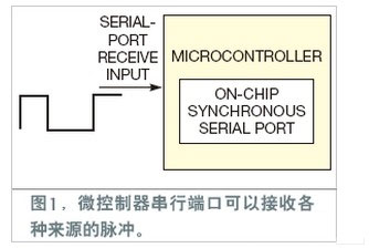
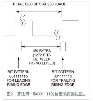
Many industrial and instrumentation systems need to measure the duration of the pulse input, such as the speed sensor, the gating and strobing pulses of the external system, and the frequency of the PWM (Pulse Width Modulation) input. Designers use on-chip timers and edge-driven interrupts. However, if these components are not available, such measurements can be made with an on-chip serial sync receiver. The baud rate of the serial receiver can be set according to the required timing accuracy. The receiver interrupts the microcontroller after every 8 bits. A pulse width acquisition routine can be inserted into the application to read the bytes received by the ISR (Interrupt Service Routine). It counts and accumulates the received 0 and 1 bytes to measure the duration of the incoming pulse (Figure 1). The algorithm measures a for the duration between two consecutive rising edges. When the microcontroller receives a byte that is neither 0xff nor 0x00, a rising or falling edge is detected. If a byte is less than 0x80H (100000b), the byte represents a rising edge. If the byte is equal to or greater than this value, the byte represents a falling edge. The leading edge of the rising edge resets the bit counter to the number of trailing 1s in the rising edge byte by shifting to the right. The bit counter increments by 8 when each byte comes in, including the one that marks the falling edge. When the counter receives a rising edge (by the next rising edge byte flag, which is greater than 0x80H but less than 00H), it again counts the number of leading zeros in that byte and adds this number to the accumulated bit counter. The accumulated bit count at this time is related to the time period of the pulse train, and its factor is equal to the baud rate. Figure 2 shows a 200 Hz pulse train with a time between the two rising edges of 5 ms. The baud rate is 356 kbaud. In a measurement cycle, the flag for the leading rising edge is assumed to be 0011 1111b. The microcontroller shifts it to the right, counts the number of trailing 1, and initializes the bit counter to 6. The time corresponding to this count is approximately 23.43 μs. Next, each byte before the rising edge byte increments the bit counter by 8. Simple calculations show that there are 159 bytes, which is 1272 bits. At this point, the total number of bits counted is 1278 bits, including the six 1s received in the first rising edge byte. The pulse chain now encounters a trailing rising edge byte with a value of 0011 1111b. To do this count, you need to shift 0 to the left and count as two bits. The total number of bits between the two rising edges is 1280 bits. At a rate of 256 kbaud, this number corresponds exactly to 5 ms or 200 Hz. This bit count concept can be modified according to your application needs. If you only need to measure low-cycle pulses, you need to detect a falling edge and accumulate the number of bits until you see a rising edge. This concept can be used to read incoming PWM signals by reading a high period of known incoming pulse frequency. It can be equipped with a scrolling display that displays 300-500 words of display content. It can also be equipped with intelligent infrared probe anti-collision device, which can automatically return to work when people or foreign objects are 20-30CM, thus ensuring the safety of vehicles and pedestrians.It can automatically open and close when automatic clutch is cut off. Manually open and close when manual clutch is cut off. The control system has control panel, push button switch, and other requirements. Equipped with wireless remote control.The door body is made of high-quality stainless steel and aluminum alloy profiles, and is hinged by the parallelogram principle. The drive is driven by special motor, worm and worm gear deceleration, and has automatic clutch or manual clutch. Factory Sliding Retractable Gate,Aluminum Alloy School Sliding Gate,Automatic Electric Single Double Gate,Store Retractable Gate Shenzhen Hongfa Automatic Door Co., Ltd. , https://www.hfautodoors.com
